and level, temperature, visual sensor (CCD, CID), contact sensor
(limit switch), non-contact sensor (proximity sensor), photoelectric
sensor, microwave sensor and laser sensor.
SENSOR / TRANDUCER
General objective : To understand the function of transducer and
sensor .
Specific objectives : At
the end of the unit you should be able to:
- List the advantages and disadvantages of transducer and sensor.
- Describe the application of transducer and sensor.
- Identify the types of transducer and sensor.
- Describe the specification of sensor and transducer.
9.1 INTRODUCTION OF
TRANSDUCER.
Transducer
is a device that changes a quantity to another quantity. It has a few elements
which are able to change a signal quantity to another signal quantity, for
example it changes the pressure to the displacement, the displacement to the
electrical movement force and others. In other words, transducer is a device
that relates the electrical to the non-electrical. Translates physical
parameters to electrical signals acceptable by the acquisition system. Some
typical parameters include temperature, pressure, acceleration, weight displacement
and velocity. Electrical quantities, such as voltage, resistance or frequency
also may be measured directly. Sensor is a part of transducer.
9.2 CLASSIFICATION OF
TRANSDUCER.
An electronic
instrumentation system consists of a number of components which together are
used to perform a measurement and record the result. An instrumentation system
generally consists of three major elements, an input device, a
signal-conditioning or processing devices, and an output device. The input
device receives the quantity under measurement and delivers a proportional
electrical signal to the signal-conditioning device. Here the signal is
amplified, filtered or otherwise modified to a format acceptable to the output
device. The output device may be simple indicating meter, an oscilloscope, or a
chart recorder for visual display. It may be a magnetic tape recorder for
temporary or permanent storage of the input data or it may be a digital
computer for data manipulation or process control. The kind of system depends
on what is to be measured and how the measurement result is to be presented.
The input quantity for most instrumentation systems is
non-electrical. In order to use electrical methods and techniques for
measurement, manipulation or control, the non-electrical quantity is converted
into an electrical signal by a device called a transducer. One definition states “a transducer is a device which,
when actuated in one transmission system, supplies energy in the same
form or in another form to a second transmission system”. This energy
transmission may be electrical, mechanical, chemical, optical or thermal..
This broad
definition of transducer includes, for example, devices that convert mechanical
force or displacement into an electrical signal. These devices form a very
large and important group of transducers commonly found in the industrial
instrumentation area, and the instrumentation engineer is primarily concerned
with this type of energy conversion. Many other physical parameters (such as
heat, light intensity, humidity) may also be converted into electrical energy
by means of transducers. These transducers provide an output signal when
stimulated by a non-mechanical input, a thermistor reacts to temperature
variations, a photocell to changes in light intensity, an electron beam to
magnetic effects, and so on. In all cases, however, the electrical output is
measured by standard methods, yielding the magnitude of the input quantity in
terms of an analog electrical measure.
Transducers may be classified according to their application, method of energy conversion, nature of the output signal and so on. All these classifications usually result in overlapping areas. A sharp distinction between and classification of types of transducers is difficult.
9.3 SPECIFICATION OF
TRANSDUCER.
In a measurement
system the transducer is the input element with the critical function of
transforming some physical quantity to a proportional electrical signal.
Selection of the appropriate transducer is therefore the first and perhaps most
important step in obtaining accurate results. A number of elementary questions
should be asked before a transducer can be selected, for example: what is the
physical quantity to be measured?, which transducer principle can best be used
to measure this quantity?, and what
accuracy is required for this measurement?
The first question
can be answered by determining the type and range of the measurand. An
appropriate answer to the second question requires that the input and output
characteristic of the transducer be compatible with the recording or
measurement system. In most cases, these two questions can be answered readily,
implying that proper transducer is selected simply by the addition of an
accuracy tolerance. In practice, this is rarely possible due to the complexity
of the various transducer parameters that affect the accuracy. The accuracy
requirements of the total system determine the degree to which individual
factors contributing to accuracy must be considered. Some of these factors are,
a. Fundamental transducer parameters – type and range of
measurand, sensitivity, excitation.
b. Physical conditions – mechanical and electrical
connection, mounting provisions, corrosion
resistance
c. Ambient conditions – nonlinearity effects, hysteresis
effects, frequency response, resolution.
d. Environment conditions – temperature effects,
acceleration, shock and vibration.
e. Compatibility of the associated equipment – zero
balance provisions, sensitivity tolerance, impedance matching, insulating resistance.
Categories (a) and
(b) are basic electrical and mechanical characteristics of the transducer.
Transducer accuracy, as an independent component, is contained in categories
(c) and (d). Category (e) considers the
transducer’s compatibility with its associated system equipment.
The total
measurement error in a transducer-activated system may be reduced to fall
within the required accuracy range by the following techniques,
a.
Using in-place system calibration with corrections
performed in the data reduction.
b.
Simultaneously monitoring the environment and
correction the data accordingly.
c.
Artificially controlling the environment to minimize
possible errors.
Some individual
errors are predictable and can be calibrated out of the system. When the entire
system is calibrated, these calibration data may then be used to correct the
recorded data. Environmental errors can be corrected by data reduction if the
environmental effects are recorded simultaneously with the actual data. Then
the data are corrected by using the known environmental characteristics of the
transducers. These two techniques can provide a significant increase in system
accuracy.
9.4 PRINCIPLES OF SENSOR/TRANSDUCERS
OPERATION.
9.4.1 DISPLACEMENT SENSOR.
a.
Diaphragm,
b.
Bellows
c.
Bourdon tube, circular or twisted.
d.
Straight tube
e.
Mass cantilever, single or double suspension.
f.
Pivot torque.

a.
Capacitive.
b.
Inductive
c.
Differential transformer
d.
Ionization
e.
Oscillation.
9.4.1.1 CAPACITIVE SENSOR.

The capacitive transducer has excellent frequency response and can measure both static and dynamic phenomena. Its disadvantages are sensitivity to temperature variations and possibility of erratic or distorted signals due to long lead length. Also, the receiving instrumentation may be large and complex and it often includes a second fixed-frequency oscillator for heterodyning purposes. The difference frequency, thus produced can be read by an appropriate output device such as an electronic counter.
9.4.1.1
INDUCTIVE
SENSOR.
In
the inductive transducer the measurement of force is accomplished by the change
in the inductance ratio of a pair of coils or by the change of inductance in a
single coil. In each case, the ferromagnetic armature is displaced by the force
being measured, varying the reluctance of the magnetic circuit. Figure 9.4.1.2
shows how the air gap is varied by a change in position of the armature. The
resulting change in inductance is a measure of the magnitude of the applied
force.

Hysteresis errors of the transducer are almost entirely limited to the mechanical components. When a diaphragm is used as the force-summing member, as shown figure 9.4.1.2(a), it may form part of the magnetic circuit. In this arrangement the overall performance of the transducer is somewhat degraded because the desired mechanical characteristics of the diaphragm must be compromised to improve the magnetic performance.
9.4.1
VELOCITY SENSOR.

9.4.1 PRESSURE AND LEVEL SENSOR.
9.4.3.1 BOURDON-TUBE PRESSURE GAUGE.
A Bourdon tube is long thin-walled cylinder of non-circular cross section sealed at one end, made from materials such as phosphor bronze, steel and beryllium-copper. A pressure applied to the inside of the tube causes a deflection of the free end, proportional to the applied pressure. The most common shape employed is the C-type, as shows in figure 9.4.3.1. Increased sensitivity can be achieved by using spiral and helical-shaped tubes. The displacement is converted into a pointer rotation over a scale by means of a gear-and-lever system. Remote indication of pressure can easily be achieved by using any of the displacement transducers.

Static and low-frequency pressure up to 500MN/m2. The frequency range is limited by the inertia of the Bourdon tube if electrical displacement transducers are used.
9.4.3.1 DIAPRAGHM PRESSURE TRANSDUCER.
For high-pressure transducers, very stiff diaphragm must be used to limit the center deflection to less than one third of the diaphragm thickness, otherwise non-linear result. For lower pressure ranges, up to a few bars, beryllium-copper corrugated diaphragm and bellow are also used to give the higher sensitivity required.

Pressure transducers using the piezo-electric effect use a similar design to the quartz load cells. The quartz discs being compressed by a diaphragm which is in direct contact with the pressure being measured. The high sensitivity of the quartz-crystal modules permits the transducers to be manufactured in extremely small size. One standing feature of quartz transducer is their high sensitivity.
Piezo-electric pressure transducers can be operated at temperatures up to 240OC, although care must be taken to compensate for zero-drift with temperature. Special water-cooled transducers are available as shown in figure 9.4.3.3. and these particularly useful for high-temperature application.

9.4.1 TEMPERATURE SENSOR.
Rf = Rref (1+ a Dt)
Where ,
Rf = resistance of the conductor at temperature t (oC)
Rref = resistance at the reference temperature, usually 0 oC.
a
= temperature coefficient of resistance.
Dt = difference between operating and reference
temperature.
Almost all metallic conductors have a positive temperature coefficient of resistance so that their resistance increases with an increase in temperature. Some materials, such as carbon and germanium, have a negative temperature coefficient of resistance that signifies that the resistance decrease with an increase in temperature. A high value of a is desirable in a temperature-sensing element so that a substantial change in resistance occurs for a relatively small change in temperature. This change in resistance (DR) can be measured with a Wheatstone bridge, which may be calibrated to indicate the temperature that caused the resistance change rather than the resistance change itself.
The sensing element of a resistance thermometer is selected according to the intended application. Platinum wire is used for most laboratory work and for industrial measurements of high accuracy. Nickel wire and copper wire are less expensive and easier to manufacture than platinum wire elements, and they are often used in low-range industrial applications.
Resistance thermometers are generally of the probe type for immersion in the medium whose temperature is to be measured or controlled. A typical sensing element for a probe-type thermometer is constructed by coating a small platinum or silver tube with ceramic material, winding the resistance wire over the coated tube, and coating the finished winding again with ceramic. This small assembly is then fired at high temperature to assure annealing of the winding and then it is placed at the tip of the probe. The probe is protected by a sheath to produce the complete sensing element.
The Wheatstone bridge has certain disadvantages when it is used to measure the resistance variations of the resistance thermometer. These are the effect of contact resistances of connections to the bridge terminals, heating of the elements by the unbalance current, and heating of the wires connecting the thermometer to the bridge. Slight modifications of the Wheatstone bridge, such as the double slide-wire bridge, eliminate most of these problems. Despite these measurement difficulties, the resistance thermometer method is so accurate that it is one of the standard method of temperature measurement within the range of -183oC to 630oC. Table 9.4.4.1 summarizes the characteristics of the three most commonly used resistance materials.


9.4.1.1
THERMOCOUPLES.
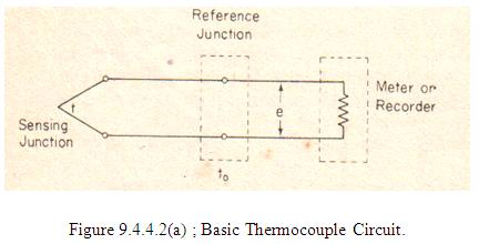
A thermocouple consists of pair of dissimilar metal wires joined together at one end ( sensing, or hot, junction) and terminated at the other end (reference, or cold, junction) which is maintained at a known constant temperature (reference temperature). When a temperature difference exists between the sensing junction and the reference junction, an emf is produced that causes a current in the circuit. When the reference junction is terminated by a meter or recording instrument, as in figure 9.4.4.2 (a), the meter indication will be proportional to the temperature difference between the hot junction and the reference junction. This thermoelectric effect, caused by contact potentials at the junctions, is known as the Seeback Effect.
To ensure long life in its operating environment, a thermocouple is protected in an open or closed end metal protecting tube or well. To prevent contamination of couple when precious metals are used (platinum and its alloys), the protecting tube is both chemically inert and vacuum tight. Since the thermocouple is usually in a location remote from the measuring instrument, connections are made by means of special extension wires called compensation wires. Maximum accuracy of measurement is assured when the compensating wires are of the same material as the thermocouple wires.
The simplest temperature measurement using a thermocouple is by connecting a sensitive millivoltmeter directly across the cold junction. The deflection of the meter is then almost directly proportional to the difference in temperature between the hot junction and the reference junction. The simple instrument has several serious limitations, mainly because the thermocouple can only supply very limited power to drive the meter movement.
The most common method in thermocouple temperature measurements involves using a potentiometer.
9.4.1.1
THERMISTOR.
Thermistors or thermal resistors are semiconductor devices that behave as resistors with a high , usually negative, temperature coefficient of resistance. In some cases, the resistance of a thermistor at room temperature may decrease as much as 6 per cent for 1OC rise in temperature. This high sensitivity to temperature change makes the thermistor extremely well suited to precision temperature measurement, control and compensation. Thermistors are therefore widely used in such applications, especially in the lower temperature range of -100OC to 300 OC.
Thermistor are composed of a sintered mixture of metallic oxides, such as manganese, nickel, cobalt, copper, iron and uranium. Smallest in size are the beads with a diameter of 0.15mm to 1.25mm. Beads may be sealed in the tips of solid glass rods to form probes that are somewhat easier to mount than beads. Disks and washers are made by pressing thermistor material under high pressure into flat cylindrical shapes with diameter from 2.5 mm to 25mm.Washer can be stacked and placed in series or in parallel for increased power dissipation.
Three important characteristic of thermistors make them extremely useful in measurement and control applications, the resistance-temperature characteristic, the voltage-current characteristic and the current-time characteristic.
9.4.1 PHOTOELECTRIC SENSOR.
The photoelectric transducer makes use of the properties of a photoemissive cell or phototube. The phototube is a radiant energy device that controls its electron emission when exposed to incident light. The construction of a phototube is shown in figure 9.4.5 (a), its symbol is given in the schematic diagram of figure 9.4.5(b).


The large semicircular element is the photosensitive cathode and the thin wire down the center of the tube is the anode. Both elements are placed in a high-vacuum glass envelope. When a constant voltage is applied between the cathode and the anode, the current in the circuit is directly proportional to the amount of light, or light intensity, falling on the cathode. The curves of 9.4.5 (c) show the anode characteristics of a typical high-vacuum phototube.
Notice that the voltage above approximately 20V the output current is nearly independent of applied anode voltage but depends entirely on the amount of incident light. The current through the tube is extremely small, usually in the range of a few microamperes. In most cases therefore, the phototube is connected to an amplifier to provide a useful output.
The photoelectric transducer of figure 9.4.5(d), uses a phototube and a light source separately by a small window whose aperture is controlled by the force-summing member of the pressure transducer. The displacement of the force-summing member modulates the quantity of incident light on the photosensitive element. According to the curve of figure 9.4.5 (c ), a change in light intensity varies the photoemissive properties at a rate approximately linear with displacement. This transducer can use either a stable source of light or an ac modulated light.

The advantages of this type of transducer are its high efficiency and its adaptability to measuring both static and dynamic conditions. The devices may have poor long-term stability, does not respond to high frequency light variations, and requires a large displacement of the force-summing member.
9.4.1 LASER VELOCIMETERS.

A sensor viewing this point sees a small circular fringe pattern that varies in amplitude as scattering changes. If the medium is moving across the field of view, the sensor detects passing fringes and produces short bursts of signal. The period of the cycles in a burst is a measure of the velocity. Extensive electronic processing is needed to produce accurate flow measurements on such vague signals. The main advantages of laser flow meters is that the velocity of a volume of fluid only 10-3 mm3 is viewed. The method is most useful in turbulence and profile studies. It is essential that some, but not many scattering particles exist to provide a signal for the detector. Often air bubbles or a colloidal solid are injected to enhance the signal strength.